Guide no. 93
A 38 kHz receiver and the IRremote library: read the codes of any remote, even the TV one, and use the keys to turn on an LED, change the color of an RGB LED and move a servo.
By Ada Intelisano · informaticait.it technical team
- The receiver has three pins: S to pin 2, + to 5 V, − to GND.
- The IRremote library turns every key into protocol, address and command.
- The first sketch reads the commands of any remote: you copy them into the others.
- On the UNO, IRremote takes the PWM of pins 3 and 11, the Servo library that of pins 9 and 10.
Every remote control talks with a light our eyes can't see. In this guide Arduino learns to listen to it. You'll read the key codes of any remote, even the TV one, and use them to turn on an LED, change the color of an RGB LED and turn the arm of a servo.
1Get the parts ready
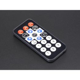
- the remote control kit with receiver for 38 kHz: remote, receiver on a small board and a three-wire jumper
- Arduino UNO (a compatible board is fine) with its USB cable
- a 400-point breadboard, male-to-female and male-to-male jumper wires
- from step 8: the KY-009 RGB LED module, three 330 Ω resistors and an SG90 micro servo
2How the signal travels
Inside the receiver there is a light sensor, an amplifier and a filter tuned to 38 kHz: it keeps the light that flashes 38,000 times a second and rejects the steady light of the sun or of light bulbs. What reaches the S pin is already a clean series of bursts: at rest the pin is high, and during each burst it drops to 0 V. The IRremote library does the rest: it measures how long the bursts and pauses last and gets three pieces of information out of them.
3Install the IRremote library
In the Arduino IDE open the Library Manager, search for IRremote and install the one by shirriff, z3t0, ArminJo. Our sketches are tested with version 4.7.1.
Watch out for old examples you find online: if they contain irrecv.decode(&results) they were written for version 2 of the
library and don't work with the current one.
4Connect the receiver
The breadboard shares out the 5 V and ground: soon three parts will use them. Follow the drawing below.
- 5V on the UNO → top + rail of the breadboard (red wire), GND → top − rail (black wire). Both wires run around the left side of the board.
- The receiver stays off the breadboard, connected with three male-to-female jumper wires: − to the − rail, the middle pin (+) to the + rail, S to column 21, row j.
- A short yellow jumper from f to e in column 21 takes the signal to the lower half. From row a of the same column a jumper wire goes to pin 2.
The small board has S and − printed on it; the middle pin, with no marking, is the +. Check the markings on your module before wiring it: the pin order changes from one manufacturer to another.
5Read the key codes
// Press a key on the remote: Arduino writes its code in the Serial Monitor.
#include <Arduino.h>
#include <IRremote.hpp>      // the IRremote library

const int IR_PIN = 2;        // the S pin of the receiver

void setup() {
  Serial.begin(115200);
  IrReceiver.begin(IR_PIN, ENABLE_LED_FEEDBACK);   // the L LED blinks at every signal
  Serial.println("Ready: press a key on the remote");
}

void loop() {
  if (IrReceiver.decode()) {                       // has a signal arrived?
    IRData &data = IrReceiver.decodedIRData;       // what the library understood
    if (data.flags & IRDATA_FLAGS_IS_REPEAT) {
      Serial.println("  ...key held down");
    } else if (data.protocol == UNKNOWN) {
      Serial.println("Signal not recognized: try again");
    } else {
      Serial.print("Protocol: ");
      Serial.print(getProtocolString(data.protocol));
      Serial.print("   address: 0x");
      Serial.print(data.address, HEX);
      Serial.print("   command: 0x");
      Serial.println(data.command, HEX);
    }
    IrReceiver.resume();                           // ready for the next key
  }
}
Upload the sketch, open the Serial Monitor at 115200 and point the remote at the receiver. Press one key at a time, without rushing.
address: 0x... and command: 0x... (the numbers depend on your remote). The board's L LED blinks when the light arrives. If you hold a key down you get ...key held down.0x10 is a number written in base 16: the 0x in front tells you so. No math needed: copy it as it is, with the 0x, into the table below.Write your codes here (you'll need them in steps 7, 9 and 10):
| Key | Command on your remote | Adafruit 389 mini remote |
|---|---|---|
| 1 | 0x10 | |
| 2 | 0x11 | |
| 3 | 0x12 | |
| 0 | 0x0C | |
| left arrow | 0x08 | |
| right arrow | 0x0A | |
| OK (called Enter on the 389) | 0x09 |
Adafruit 389 column: commands we worked out from the codes Adafruit publishes for this remote. They are the numbers already written in the sketches.
- No lines at all: check the S wire on pin 2, + and − on the right rails, and the 115200 speed at the bottom of the Serial Monitor.
- Is the remote new? See whether a plastic tab is insulating the battery: pull it out (the Adafruit mini remote has one).
- “Signal not recognized” on every key: move closer, the signal may be arriving weak; if nothing changes, that remote uses a protocol the library doesn't know.
6Try the TV remote
Grab the remotes around the house: TV, set-top box, stereo. The library recognizes
the most common protocols (NEC, Sony, RC5, RC6, Samsung, LG, Panasonic, JVC, Denon and others) and prints the name of each one. With the ones it doesn't
know you get “Signal not recognized”. Air conditioners are a special case: they send much longer messages and the library may not
recognize them, or it may print PulseDistance, meaning it understands the shape of the signal but can't split it into address and command.
A remote that flashes at a frequency other than 38 kHz is also picked up less well: the receiver's filter is tuned to that frequency.
Remember that the light reaches everything in the room: if you use the TV's volume keys to control Arduino, the TV will change its volume too.
7One key turns on the LED
// A key on the remote turns the board's L LED on and off (pin 13).
#include <Arduino.h>
#include <IRremote.hpp>

const int IR_PIN = 2;              // the S pin of the receiver
const int LED_PIN = 13;            // the L LED, already on the board
const uint16_t KEY_LED = 0x10;     // key 1 of the Adafruit 389 remote: write yours

bool ledOn = false;                // at the start the LED is off

void setup() {
  pinMode(LED_PIN, OUTPUT);
  IrReceiver.begin(IR_PIN, DISABLE_LED_FEEDBACK);  // now we control the L LED ourselves
}

void loop() {
  if (IrReceiver.decode()) {
    bool held = IrReceiver.decodedIRData.flags & IRDATA_FLAGS_IS_REPEAT;
    if (!held && IrReceiver.decodedIRData.command == KEY_LED) {
      ledOn = !ledOn;                                // off becomes on and vice versa
      digitalWrite(LED_PIN, ledOn ? HIGH : LOW);
    }
    IrReceiver.resume();
  }
}
Pick a key and write its command in place of 0x10 in the KEY_LED line. With the Adafruit 389 mini
remote leave 0x10: it's its key 1. The LED is the L LED already on the board, on pin 13: there's nothing to connect.
That's why DISABLE_LED_FEEDBACK tells the library to stop using it for blinking.
ledOn = !ledOn the exclamation mark means “the opposite”: if ledOn was true it becomes false, and vice versa. That way the same key turns the LED on and off.- Nothing happens: is the command written in the sketch really the one for that key? Check it against the table, letter by letter.
- The LED keeps turning on and off while you hold the key down: the
!heldcheck is missing from theifline.
8Add the RGB LED and the servo
The receiver stays where it is. The KY-009 module has four pins: B, G, R and − (common cathode). The markings are on the back; on our module, with the LED facing you and the pins at the bottom, the order from the left is B, G, R, −. There are no resistors on the small board: each color needs its own 330 Ω resistor (orange, orange, black, black, brown). Follow the drawing below.
- B, G and R with three male-to-female jumper wires to columns 8, 9 and 10, row j; − to the top − rail.
- The three resistors straddle the center channel, from f to e, in the same columns.
- From row a of columns 8, 9 and 10, three jumper wires go to pins 7 (blue), 6 (green) and 5 (red).
- The servo connector has three holes: push in three male-to-male jumper wires. Brown to the top − rail, red to the + rail, orange to column 5, row j. A short jumper from f to e in column 5 and a jumper wire from row a to pin 9.
9Change color with the keys
// Keys 1, 2 and 3 turn red, green and blue on and off; key 0 turns everything off.
#include <Arduino.h>
#include <IRremote.hpp>

const int IR_PIN = 2;              // the S pin of the receiver
const int RED_PIN = 5;             // R of the RGB LED module (goes through its resistor)
const int GREEN_PIN = 6;           // G
const int BLUE_PIN = 7;            // B

// the commands of keys 1, 2, 3 and 0 on the Adafruit 389 mini remote:
// with another remote write the ones you read with the first sketch
const uint16_t KEY_1 = 0x10;
const uint16_t KEY_2 = 0x11;
const uint16_t KEY_3 = 0x12;
const uint16_t KEY_0 = 0x0C;

bool red = false;
bool green = false;
bool blue = false;

void show() {                      // turns on the colors that are true
  digitalWrite(RED_PIN, red ? HIGH : LOW);
  digitalWrite(GREEN_PIN, green ? HIGH : LOW);
  digitalWrite(BLUE_PIN, blue ? HIGH : LOW);
}

void setup() {
  pinMode(RED_PIN, OUTPUT);
  pinMode(GREEN_PIN, OUTPUT);
  pinMode(BLUE_PIN, OUTPUT);
  IrReceiver.begin(IR_PIN, ENABLE_LED_FEEDBACK);
}

void loop() {
  if (IrReceiver.decode()) {
    bool held = IrReceiver.decodedIRData.flags & IRDATA_FLAGS_IS_REPEAT;
    uint16_t key = IrReceiver.decodedIRData.command;
    if (!held) {                   // a color changes only on the first press
      if (key == KEY_1) red = !red;
      if (key == KEY_2) green = !green;
      if (key == KEY_3) blue = !blue;
      if (key == KEY_0) {
        red = false;
        green = false;
        blue = false;
      }
      show();
    }
    IrReceiver.resume();
  }
}
Write the commands of your keys 1, 2, 3 and 0 in the four KEY_ lines. Each key turns one color on or off; two colors
together mix as in guide no. 46: 1 and 2 make yellow, all three make white. 0 turns everything off.
digitalWrite: seven colors plus black. If you want shades with analogWrite, pins 5 and 6 are still free. For the same reason, no tone() for a buzzer: it uses the same timer as IRremote and, as the library documentation says, reception stops after a tone().- One color never lights up: check its jumper wire and its resistor, which must go exactly from f to e in the same column.
- The colors come out swapped: your module has its pins in a different order. Follow the markings on the back, not the drawing.
10Move the servo with the arrows
// The arrows turn the servo 10 degrees at a time, OK brings it back to the center.
#include <Arduino.h>
#include <IRremote.hpp>
#include <Servo.h>

const int IR_PIN = 2;              // the S pin of the receiver
const int SERVO_PIN = 9;           // the orange wire of the servo

// the commands of the arrows and of Enter on the Adafruit 389 mini remote:
// with another remote write the ones you read with the first sketch
const uint16_t KEY_LEFT = 0x08;
const uint16_t KEY_RIGHT = 0x0A;
const uint16_t KEY_OK = 0x09;

Servo arm;
int angle = 90;                    // we start from the center

void setup() {
  arm.attach(SERVO_PIN);
  arm.write(angle);
  IrReceiver.begin(IR_PIN, ENABLE_LED_FEEDBACK);
}

void loop() {
  if (IrReceiver.decode()) {
    uint16_t key = IrReceiver.decodedIRData.command;     // also while a key is held down
    if (key == KEY_LEFT) angle = angle + 10;
    if (key == KEY_RIGHT) angle = angle - 10;
    if (key == KEY_OK) angle = 90;
    angle = constrain(angle, 0, 180);                    // never below 0 or above 180
    arm.write(angle);
    IrReceiver.resume();
  }
}
Write the commands of your arrows and of the OK key in the three KEY_ lines.
Here the repeats come in handy: as long as you hold an arrow down the remote keeps sending the signal and the arm moves
10 degrees at a time. constrain keeps the angle between 0 and 180; OK brings it back to 90.
- The arm turns the wrong way: swap
+ 10and- 10in the lines of the two arrows. - The servo moves in jerks or the board restarts: Adafruit says this can be a power problem and that some USB ports don't supply enough current for the board and the servo together. Try another port or a power supply.
- The receiver gets things wrong only while the servo is moving: the motor can disturb the 5 V. For a noisy power supply, Vishay, the maker of the receiver, recommends a resistor in series on the receiver's + and a capacitor between its + and its −.
11Other receivers
You can also get the receiver without a board, for example our 1838 in packs of three or the Vishay TSOP38238. It goes straight into the breadboard: with the lens facing you the legs are, from the left, OUT, GND and VCC. OUT goes to pin 2, GND to the − rail, VCC to the + rail. According to the TSOP382 datasheet the output pull-up resistor is already inside the receiver: you don't need to add one.
The Seeed Studio Grove receiver uses the same Vishay part and a four-wire cable: yellow is the signal, red VCC, black GND, white not connected.
12Challenge yourself
- Combine the two sketches: arrows for the servo, 1, 2 and 3 for the colors. The
setup()lines go together, the key checks inside the sameif. - Make a parking barrier: OK raises the arm to 90 degrees, waits 3 seconds and goes back to 0.
- Check the address too, with
&& IrReceiver.decodedIRData.address == ...: that way another remote with the same commands won't interfere.
- the receiver filters the light at 38 kHz and gives clean pulses on the S pin;
- IRremote turns every key into protocol, address and command: the command is the number to use;
- with the first sketch you read the commands of any remote, then you write them into the others;
- the repeats of a key held down can be thrown away or put to use.
Useful products


- New
- Made to order
- New
- Made to order

- New
- Made to order


- New
- Made to order


Other guides
- Resistor colour code and tolerances
- N-channel and P-channel MOSFETs
- Bipolar transistor (BJT) or MOSFET?
- Relays: how to drive them and how much current they draw
- THT and SMD/SMT components
- XIAO board pinouts
- LEDs: forward voltage and series resistor
- The multimeter: measuring voltage and current
- Wemos D1 mini: first steps
- MOSFET module with Arduino and ESP32
- Relay module with Arduino and ESP32
- 3D printing filaments: PLA, PETG and fibre-filled versions
- Analog and digital: the differences
- ADS1115: 16-bit converter with Arduino and ESP32
- From bits to real values: converting sensor readings
- DS3231 RTC clock with Arduino and ESP32
- Linear or switching regulator: which one to choose
- Step-down, step-up and buck-boost: choosing the right module
- Voltage divider: reading voltages higher than 5 V or 3.3 V
- Pull-up, pull-down and bounce: wiring a button properly
- 3.3 V and 5 V logic levels: getting an ESP32 and an Arduino to talk
- The I²C bus: addresses, pull-ups and the scanner
- Lithium batteries: voltages, charging and protection
- ESP32 power consumption and deep sleep: how long the battery lasts
- Temperature sensors compared
- ESP32: which pins to use and which to avoid
- Getting started with the ESP32 in Arduino IDE 2 and PlatformIO
- SSD1306 OLED display and 16×2 I²C LCD with Arduino and ESP32
- PIR motion sensor and HC-SR04 ultrasonic sensor
- Date and time from the Internet with the ESP32: NTP, Italian time zone and daylight saving time
- MicroSD data logger: saving measurements to CSV
- Solar-powered ESP32: panel, charger and the numbers for Italy
- Web server on the ESP32: control a relay from your phone
- Your first LED: wire it up and make it blink
- The button: let Arduino decide
- The potentiometer: turn a knob and read its value
- Soft light: adjusting the brightness of an LED
- The buzzer: playing notes and melodies
- The traffic light: three LEDs in sequence
- The thermometer: reading the temperature with the TMP36
- The servo motor: moving an arm with Arduino
- The night light: the photoresistor and your first decision
- The relay: switching on a light bulb with Arduino
- The LCD display: making Arduino write
- The electronic dice: your first complete project
- The RGB LED: every color from three lights
- The joystick: two-axis control with a shield
- The LED ring: twelve colors from a single pin
- The DC motor: driving it with a MOSFET
- Soil moisture: the plant that asks for water
- The stepper motor: turn exactly as far as you want
- The parking sensor: faster and faster beeps
- The 7-segment display: big, bright numbers
- Automatic watering: the plant that waters itself
- The keypad: a lock with a secret code
- Networked weather station: values and chart on your phone
- A Telegram bot on the ESP32: your home from your phone
- MQTT with the ESP32: the language of connected devices
- Updating the ESP32 over Wi-Fi (OTA)
- ESP-NOW: two ESP32 boards talking without a router
- WebSocket with the ESP32: the LED that follows the slider
- Readings on a Google sheet, with deep sleep
- WiFiManager: choose the Wi-Fi from your phone
- Bluetooth LE with the ESP32: the phone without a network
- The camera in your browser with the ESP32-S3
- A portable Bluetooth speaker you build yourself
- Bluetooth desktop speakers, 2 × 20 W
- Stereo MP3 player with two buttons
- The shelf that plays music: a Visaton exciter
- How to solder well
- How much does it draw? Current and power with the INA219
- Load-cell scale with the HX711
- CO2 traffic light: when to open the windows
- RFID card door opener
- GPS: track logger on microSD
- LoRa: how far does it go? A range test with two boards
- Battery weather sign with an e-paper display
- Web radio with an ESP32 and an I2S amplifier
- Getting started with the Raspberry Pi Pico 2 in MicroPython
- Your first amplifier: the LM386 and a speaker
- Talking Arduino: the DFR0760 speech synthesis module
- The spectrum of your music on an LED matrix
- Drawing with 64 LEDs: the 8×8 matrix with the MAX7219
- A real voltage: the 12-bit MCP4725 DAC
- Your own macro keyboard: four NeoKey keys and the QT Py RP2040
- The Maqueen robot with the micro:bit: follow the line, avoid obstacles
- A two-way speaker with a Visaton woofer, tweeter and crossover
- A 120-LED NeoPixel strip, powered the right way
- A linear actuator to open a lid
- The heartbeat on Arduino: an ECG with the AD8232
- The electronic spirit level: tilt and impacts with the ADXL345