Guide no. 89
The small 6 V DFRobot electric push rod with Arduino UNO and the DRV8833 driver: two buttons, the current read by the driver to stop at the end, the rest breaks.
By Ada Intelisano · informaticait.it technical team
- The actuator is a small motor that pushes a rod: swap the two wires and the rod extends or retracts. DFRobot states 6 V and 128 N of thrust; the label also says 7 mm/s.
- DFRobot doesn't say how much current it draws or whether there are limit switches inside: that is why we use Adafruit's DRV8833, which limits the current to about 1 A per bridge.
- The AS pin of the driver puts out 0.2 V per amp: Arduino reads it and stops the motor when the rod reaches the end or hits an obstacle.
- The label shows a 10 %: we read it as a duty cycle, and the sketch makes the actuator rest nine times as long as it moved.
A linear actuator turns the rotation of a small motor into a push in a straight line: the rod extends, stops, retracts. With one of these you can open the lid of a box, a hatch, an air vent. Here we use the 6 V DFRobot actuators, which come with four different strokes, and we control them from an Arduino UNO with two buttons, OPEN and CLOSE. The most interesting part is the one you can't see: how to stop at the end without knowing how much current the motor draws, because DFRobot doesn't publish it.
1The parts
- a 6 V DFRobot linear actuator: FIT0803 (10 mm stroke), FIT0804 (30 mm), FIT0805 (50 mm) or FIT0806 (100 mm). The examples use the FIT0805;
- Arduino UNO R3 with its USB cable;
- the Adafruit DRV8833 driver (3297), with the header to solder;
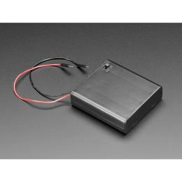
- a 4 × AA battery holder with an on/off switch (Adafruit 830) and four batteries;
- two 6 mm pushbuttons, a breadboard, male-to-male jumper wires.
2How it's made and how far it extends
The four models share the same body; what changes is the stroke, that is how far the rod comes out. For mounting, what counts is the distance between the centers of the two 4 mm holes, the one in the ear on the body and the one in the eye of the rod. From DFRobot's drawing: retracted it is 54.5 mm plus the stroke, extended it is one stroke more. The body is 20 mm high, the tube 16 mm. The cable is red and black and ends in a 2-pin female connector.
| Model | Stroke | Hole to hole, retracted | Extended | One stroke at 7 mm/s (calculation) |
|---|---|---|---|---|
| FIT0803 | 10 mm | 64.5 mm | 74.5 mm | 1.4 s |
| FIT0804 | 30 mm | 84.5 mm | 114.5 mm | 4.3 s |
| FIT0805 | 50 mm | 104.5 mm | 154.5 mm | 7.1 s |
| FIT0806 | 100 mm | 154.5 mm | 254.5 mm | 14.3 s |
DFRobot states 6 V and a thrust of 128 N, roughly the weight of 13 kg (our calculation). The speed, 7 mm/s, is on the FIT0803 page and on the labels of all four, without saying under what load: the times in the table are only indicative, and with a weight to push the rod may move more slowly. The label also shows IP54, a rating for protection against dust and water that applies to the actuator, not to Arduino and the driver.
What DFRobot does not say matters just as much: how much current it draws, with no load and with the rod stalled; whether there are limit switches inside that cut off the motor at the end; which way the rod moves with red on +. Then there is a “10%”, which on the FIT0803 page is called “Frequency”. We read it as a duty cycle: the actuator moves for at most one tenth of the time and rests for the remainder. That is our interpretation; DFRobot doesn't explain it.
3Why the DRV8833
An Arduino pin can't drive a motor (guide no. 49), and here you also need to reverse the direction: that takes an H-bridge. Choosing one is easy when you know the motor current. Here we don't, so we look for a driver that protects itself and protects the actuator too.
| Drivers in our catalog | With this actuator |
|---|---|
| Adafruit DRV8833 (3297) | Motors from 2.7 to 10.8 V. Current limit already set on the board, about 1 A per bridge; protection against overcurrent, overheating and undervoltage; the AS pin to read the current. Our choice. |
| TB6612FNG (Adafruit 2448, DFRobot DRI0044, SparkFun 14450) | Right voltage, 1.2 A average and 3.2 A peak. Toshiba states thermal and undervoltage protection, not a current limit: it's fine when the motor current is known. |
| DRV8871 (Adafruit 3190) | Works from 6.5 V up: at 6 V it is below the minimum. |
| L9110H (Adafruit 4489) | Adafruit rates it for 800 mA: little margin with a current we don't know. |
On the Adafruit board two 0.2 Ω resistors measure the current of the two bridges. When the voltage across one of them reaches 0.2 V the chip switches that bridge off for a moment, until the next cycle of its internal PWM (TI): 0.2 V divided by 0.2 Ω is 1 A, the limit set by Adafruit. If the rod stays stuck at the end, the motor gets about 1 A at most instead of all the current it would ask for. The same point comes out on the AS pin: Arduino reads it on A0 and knows how much current is flowing.
The SLP pin is held low on the board, and as long as it stays low the driver sleeps. We control it with pin 10: awake only while the rod is moving, so at rest the chip draws a few microamps and the batteries last longer.
| AIN1 | AIN2 | The motor |
|---|---|---|
| 0 | 0 | free: the outputs are disconnected |
| 1 | 0 | turns one way (AOUT1 high, AOUT2 low) |
| 0 | 1 | turns the other way |
| 1 | 1 | braked: both outputs low |
4The wiring
- Buttons straddling the center channel: OPEN in columns 2 and 4, CLOSE in columns 6 and 8. Pin 2 to OPEN, pin 3 to CLOSE; the other leg of each button goes to the − rail.
- Driver straddling the channel, with the terminal block to the right: the header in row d (AIN1 in column 11, VM in 18), the row with AOUT and AS in row g.
- Pin 8 → AIN1, pin 9 → AIN2, pin 10 → SLP. The driver's GND goes to the − rail, and the − rail to the UNO's GND.
- AS (column 16, row j) → A0, with the light blue wire running underneath.
- Actuator: two jumper wires from the driver to its connector, AOUT1 to red and AOUT2 to black.
- Batteries in the VMotor terminal block: red to +, black to −. Keep the switch off until you have checked everything.
- The batteries go in the VMotor terminal block, which has reverse-polarity protection. The VM pin on the header is not protected (Adafruit).
- The actuator never takes power from Arduino's 5V: the motor current comes only from the batteries.
- All the GNDs connected together: driver, − rail, UNO. Without this, A0 reads random numbers.
5First test: out, in and the current
Put the stroke of your model in STROKE_MM. The
sketch works out the time for one stroke at 7 mm/s, adds 30 % (our margin), extends the rod, waits three seconds and
retracts it. Meanwhile, every 100 ms, it writes the time and the current to the Serial Monitor (115200 baud).
analogRead measures from 0 to 5 V in 1024 steps, almost 5 mV per step. On the AS pin there are only a few tenths of a volt, so we switch to the UNO's internal reference, 1.1 V: each step is worth about 1 mV. Arduino warns that the first readings after the change are not accurate, and the sketch throws away five of them.// Linear actuator test: the rod extends, stops, retracts. Every 100 ms the // Serial Monitor shows the current read on the AS pin of the DRV8833 driver. #include <Arduino.h> const byte AIN1 = 8; // the two inputs of bridge A const byte AIN2 = 9; const byte SLP = 10; // HIGH = driver awake, LOW = driver asleep const byte SENSE = A0; // AS pin: 0.2 V for every amp through the motor const unsigned int STROKE_MM = 50; // the stroke of your actuator: 10, 30, 50 or 100 // time for one stroke: stroke divided by 7 mm/s (DFRobot figure), plus a 30 % margin const unsigned long TIME_MS = STROKE_MM * 1300UL / 7; int currentMA() { long sum = 0; for (byte i = 0; i < 20; i++) sum += analogRead(SENSE); float mV = sum / 20.0 * 1100.0 / 1024.0; // average in millivolts, 1.1 V scale return (int)(mV * 5); // 1 mV across 0.2 ohm = 5 mA } void drive(int dir) { // 1 = out, -1 = in, 0 = stop digitalWrite(AIN1, dir > 0 ? HIGH : LOW); digitalWrite(AIN2, dir < 0 ? HIGH : LOW); } void stroke(int dir) { Serial.println(dir > 0 ? "OUT" : "IN"); digitalWrite(SLP, HIGH); delay(2); // the DRV8833 wakes up within 1 ms drive(dir); unsigned long start = millis(); while (millis() - start < TIME_MS) { char line[32]; snprintf(line, sizeof line, "%5lu ms %4d mA", millis() - start, currentMA()); Serial.println(line); delay(100); } drive(0); digitalWrite(SLP, LOW); } void setup() { pinMode(AIN1, OUTPUT); pinMode(AIN2, OUTPUT); pinMode(SLP, OUTPUT); Serial.begin(115200); analogReference(INTERNAL); // scale from 0 to 1.1 V, not 0 to 5 V for (byte i = 0; i < 5; i++) analogRead(SENSE); // the first readings don't count stroke(1); delay(3000); stroke(-1); Serial.println("Done. To repeat, press RESET after a few minutes of rest."); } void loop() { }
6Read the numbers
At start-up you see a short peak: that is the motor's inrush current. Then the current drops and stays more or less steady while the rod travels. Watch closely what happens when the rod reaches the end:
- the current drops to zero: inside the actuator there is a limit switch that cuts off the motor;
- the current rises and stays high: the motor pushes against the end and the driver keeps it below its limit. Better to stop before that, and that is what the sketch in step 7 does.
Write down two numbers: the current during the stroke and the current at the end. You need them for the threshold. They are estimates, because the internal reference of the UNO is not as accurate as an instrument: for a true value use the multimeter in series (guide no. 8).
- It doesn't move and the current is 0: the battery holder switch is off, SLP doesn't reach pin 10, or the common GND is missing.
- With “OUT” the rod retracts: swap the two jumper wires in the actuator connector.
- It moves but the current stays at 0: the light blue wire is on BS instead of AS, or it doesn't reach A0.
- Before repeating the test, let the actuator rest for a few minutes: that is the 10 % from step 2.
7The lid with two buttons
OPEN extends the rod, CLOSE retracts it. The motor stops for the first of three reasons:
- you press any button while it is moving;
- the current stays above
THRESHOLD_MAfor more than 150 ms: the rod is at the end or has hit an obstacle. In the first 300 ms this doesn't count, because at start-up the current is high anyway; - the maximum time runs out, calculated as in the test.
Then the actuator rests for nine times as long as it moved, and meanwhile the L LED blinks: that is the 10 % on the label read as a duty cycle (our proposal). After a 7-second stroke, about a minute of rest. The sketch also remembers where it stopped: when open it ignores OPEN, when closed it ignores CLOSE. At power-up it doesn't know and accepts both.
// The lid: OPEN and CLOSE with two buttons. The motor stops for three reasons:
// a press on a button, a current that is too high (rod at the end or against an
// obstacle) or the maximum time. After each stroke the actuator rests.
#include <Arduino.h>

const byte B_OPEN = 2;        // buttons to GND, with the internal pull-up
const byte B_CLOSE = 3;
const byte AIN1 = 8;
const byte AIN2 = 9;
const byte SLP = 10;
const byte SENSE = A0;        // AS pin of the driver: 0.2 V for every amp

const unsigned int STROKE_MM = 50;                       // the stroke of your actuator
const unsigned long MAX_TIME = STROKE_MM * 1300UL / 7;  // stroke / 7 mm/s, +30 %
const int THRESHOLD_MA = 800;        // above this current the rod is stalled
const unsigned long INRUSH_MS = 300; // at start-up the current is high: ignore it
const byte REST_X = 9;               // rest = 9 times the moving time (10 %)

struct Button {
  byte pin;
  bool pressed;               // stable state
  bool reading;               // last reading
  unsigned long changed;      // when the reading changed
};
Button openBtn = {B_OPEN, false, false, 0};
Button closeBtn = {B_CLOSE, false, false, 0};

enum State { IDLE, OPENING, CLOSING, RESTING };
State state = IDLE;
char position = '?';          // O open, C closed, M midway, ? unknown
unsigned long start;          // start of the movement or of the rest
unsigned long rest;           // how long the rest must last
unsigned long normal;         // last moment with the current below threshold
int peak;                     // highest current seen after the inrush

bool tapped(Button &b) {      // true only once, when the button is pressed
  bool now = digitalRead(b.pin) == LOW;
  if (now != b.reading) {
    b.reading = now;
    b.changed = millis();
  }
  if (millis() - b.changed > 30 && b.pressed != b.reading) {   // stable for 30 ms
    b.pressed = b.reading;
    return b.pressed;
  }
  return false;
}

int currentMA() {
  long sum = 0;
  for (byte i = 0; i < 20; i++) sum += analogRead(SENSE);
  float mV = sum / 20.0 * 1100.0 / 1024.0;
  return (int)(mV * 5);
}

void go(State s) {
  state = s;
  digitalWrite(SLP, HIGH);
  delay(2);
  digitalWrite(AIN1, s == OPENING ? HIGH : LOW);
  digitalWrite(AIN2, s == CLOSING ? HIGH : LOW);
  start = normal = millis();
  peak = 0;
  Serial.println(s == OPENING ? "Opening" : "Closing");
}

void halt(const char *reason, char where) {
  digitalWrite(AIN1, LOW);
  digitalWrite(AIN2, LOW);
  digitalWrite(SLP, LOW);
  unsigned long duration = millis() - start;
  position = where;
  rest = duration * REST_X;
  start = millis();
  state = RESTING;
  char line[72];
  snprintf(line, sizeof line, "Stopped (%s) after %lu ms, peak %d mA, rest %lu s",
           reason, duration, peak, rest / 1000);
  Serial.println(line);
}

void setup() {
  pinMode(B_OPEN, INPUT_PULLUP);
  pinMode(B_CLOSE, INPUT_PULLUP);
  pinMode(AIN1, OUTPUT);
  pinMode(AIN2, OUTPUT);
  pinMode(SLP, OUTPUT);
  pinMode(LED_BUILTIN, OUTPUT);
  Serial.begin(115200);
  analogReference(INTERNAL);
  for (byte i = 0; i < 5; i++) analogRead(SENSE);
  Serial.println("Ready");
}

void loop() {
  bool o = tapped(openBtn);
  bool c = tapped(closeBtn);
  unsigned long now = millis();
  if (state == OPENING || state == CLOSING) {
    char endPos = state == OPENING ? 'O' : 'C';
    unsigned long t = now - start;
    int mA = currentMA();
    if (t > INRUSH_MS && mA > peak) peak = mA;
    if (t < INRUSH_MS || mA < THRESHOLD_MA) normal = now;
    if (o || c) halt("button", 'M');
    else if (now - normal > 150) halt("high current", endPos);
    else if (t > MAX_TIME) halt("max time", endPos);
  } else if (state == RESTING) {
    digitalWrite(LED_BUILTIN, (now / 250) % 2 ? HIGH : LOW);   // the L LED blinks
    if (now - start > rest) {
      state = IDLE;
      digitalWrite(LED_BUILTIN, LOW);
      Serial.println("Ready");
    }
  } else if (o && position != 'O') {
    go(OPENING);
  } else if (c && position != 'C') {
    go(CLOSING);
  }
}
8Adjust the threshold
THRESHOLD_MA = 800 is our starting value. Mount the lid
(step 9), then open it and stop it halfway with a button: the “peak” the sketch writes on that line is the highest current of the
stroke, with the real load. Set the threshold halfway between that peak and the current you saw at the end in the test of step 6.
If in that test the current dropped to zero at the end, the threshold only matters for obstacles: keep it a little above the peak.
- It stops right after starting with “high current”: the threshold is too low for your load, raise it.
- It reaches the end and hums until “max time”: the threshold is too high, lower it but keep it above the peak of the stroke.
- The buttons don't respond: it is resting (L LED blinking), or the lid is already open or already closed and you need the other button.
9Mounting it on the lid
The actuator must be free to pivot at both ends: one pivot in the ear, fixed to the box, and one in the eye of the rod, fixed to the lid. For the 4 mm holes, an M3 screw with a self-locking nut, snug but not clamped, works as a pivot (our proposal). This way the rod pushes only along its axis, with no sideways forces.
In the drawing the hinge is on the left, the pivot on the lid 60 mm from it and the fixed pivot 104.5 mm lower, that is the retracted hole-to-hole distance of the FIT0805. When the rod extends by 50 mm the lid opens by about 53° (our calculation, indicative measurements). With the pivot closer to the hinge the lid opens wider, but it takes more force.
DFRobot doesn't say whether the rod holds its position when the motor is off and a weight pushes on it: try it with your lid before you rely on it.
- The lid closes with a push that can reach 128 N: keep your fingers away from the edge. The current limit and the threshold help, but they are not a safety device.
- Connect the FLT pin of the driver to a free pin with
INPUT_PULLUPand write “fault” when it goes low: TI pulls it low for overcurrent and overheating. - An air vent that opens above 28 °C, with the TMP36 from guide no. 40.
- A second actuator on bridge B: BIN1, BIN2, BOUT1, BOUT2, and BS for the current.
- the actuator changes direction if you swap the two wires: you need an H-bridge;
- if the motor current isn't stated, choose a driver that limits it by itself;
- the voltage across a 0.2 Ω resistor tells you how much current is flowing, and when the rod is stalled;
- the 10 % on the label, read as a duty cycle, means moving a little and resting a lot.
Useful products
- New
- Made to order

- New
- Made to order

- New
- Made to order

- New
- Made to order

- New
- Made to order

- New
- Made to order

- New
- Made to order
Other guides
- Resistor colour code and tolerances
- N-channel and P-channel MOSFETs
- Bipolar transistor (BJT) or MOSFET?
- Relays: how to drive them and how much current they draw
- THT and SMD/SMT components
- XIAO board pinouts
- LEDs: forward voltage and series resistor
- The multimeter: measuring voltage and current
- Wemos D1 mini: first steps
- MOSFET module with Arduino and ESP32
- Relay module with Arduino and ESP32
- 3D printing filaments: PLA, PETG and fibre-filled versions
- Analog and digital: the differences
- ADS1115: 16-bit converter with Arduino and ESP32
- From bits to real values: converting sensor readings
- DS3231 RTC clock with Arduino and ESP32
- Linear or switching regulator: which one to choose
- Step-down, step-up and buck-boost: choosing the right module
- Voltage divider: reading voltages higher than 5 V or 3.3 V
- Pull-up, pull-down and bounce: wiring a button properly
- 3.3 V and 5 V logic levels: getting an ESP32 and an Arduino to talk
- The I²C bus: addresses, pull-ups and the scanner
- Lithium batteries: voltages, charging and protection
- ESP32 power consumption and deep sleep: how long the battery lasts
- Temperature sensors compared
- ESP32: which pins to use and which to avoid
- Getting started with the ESP32 in Arduino IDE 2 and PlatformIO
- SSD1306 OLED display and 16×2 I²C LCD with Arduino and ESP32
- PIR motion sensor and HC-SR04 ultrasonic sensor
- Date and time from the Internet with the ESP32: NTP, Italian time zone and daylight saving time
- MicroSD data logger: saving measurements to CSV
- Solar-powered ESP32: panel, charger and the numbers for Italy
- Web server on the ESP32: control a relay from your phone
- Your first LED: wire it up and make it blink
- The button: let Arduino decide
- The potentiometer: turn a knob and read its value
- Soft light: adjusting the brightness of an LED
- The buzzer: playing notes and melodies
- The traffic light: three LEDs in sequence
- The thermometer: reading the temperature with the TMP36
- The servo motor: moving an arm with Arduino
- The night light: the photoresistor and your first decision
- The relay: switching on a light bulb with Arduino
- The LCD display: making Arduino write
- The electronic dice: your first complete project
- The RGB LED: every color from three lights
- The joystick: two-axis control with a shield
- The LED ring: twelve colors from a single pin
- The DC motor: driving it with a MOSFET
- Soil moisture: the plant that asks for water
- The stepper motor: turn exactly as far as you want
- The parking sensor: faster and faster beeps
- The 7-segment display: big, bright numbers
- Automatic watering: the plant that waters itself
- The keypad: a lock with a secret code
- Networked weather station: values and chart on your phone
- A Telegram bot on the ESP32: your home from your phone
- MQTT with the ESP32: the language of connected devices
- Updating the ESP32 over Wi-Fi (OTA)
- ESP-NOW: two ESP32 boards talking without a router
- WebSocket with the ESP32: the LED that follows the slider
- Readings on a Google sheet, with deep sleep
- WiFiManager: choose the Wi-Fi from your phone
- Bluetooth LE with the ESP32: the phone without a network
- The camera in your browser with the ESP32-S3
- A portable Bluetooth speaker you build yourself
- Bluetooth desktop speakers, 2 × 20 W
- Stereo MP3 player with two buttons
- The shelf that plays music: a Visaton exciter
- How to solder well
- How much does it draw? Current and power with the INA219
- Load-cell scale with the HX711
- CO2 traffic light: when to open the windows
- RFID card door opener
- GPS: track logger on microSD
- LoRa: how far does it go? A range test with two boards
- Battery weather sign with an e-paper display
- Web radio with an ESP32 and an I2S amplifier
- Getting started with the Raspberry Pi Pico 2 in MicroPython
- Your first amplifier: the LM386 and a speaker
- Talking Arduino: the DFR0760 speech synthesis module
- The spectrum of your music on an LED matrix
- Drawing with 64 LEDs: the 8×8 matrix with the MAX7219
- A real voltage: the 12-bit MCP4725 DAC
- Your own macro keyboard: four NeoKey keys and the QT Py RP2040
- The Maqueen robot with the micro:bit: follow the line, avoid obstacles
- A two-way speaker with a Visaton woofer, tweeter and crossover
- A 120-LED NeoPixel strip, powered the right way
- The heartbeat on Arduino: an ECG with the AD8232